Data Flow
Contents Hide
Data Flow
By double-clicking the Data Flow element under the BXP project tree, the Data Flow Panel will appear. The Data Flow Panel is used to display a visual view of data flow between client mobile device tables and server side data sources. Through the Data Flow Panel, the flow of data can be defined graphically between sync points. Sync points are data sources in which data can be sent and/or received. Sync points can be client tables on devices and/or back-end data sources on the server such as server tables in a database and/or files. Hence if the developed application requires data communication between client devices and server side systems, the data flow must be defined accordingly to allow for this exchange of data within the process of synchronisation to take place correctly. Additionally, if the BXP project requires the use of synchronisation, the project and its associated Data Flow element should be deployed onto a BrightServer instance. When the device running the BXP application connects to BrightServer to synchronise, logic defined in the Data Flow panel will then be used accordingly.
Essentially, the data flow element provides a simplified view of the server configuration, and contains the necessary configuration design data to perform synchronisation. In order for synchronisation to be carried out, the sync points of data sources and destinations need to be defined in order to deliver data to their correct places. The Data Flow element in BXP projects provide easy to use mechanisms to create the client tables and data accessors that will be interacting with data during synchronisation.
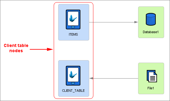
Client table nodes are sync points that represent the tables in the mobile application when executed on the devices out in the field. These nodes essentially represent the data of that client table on devices. These nodes can then be linked to data accessors in order to send and/or receive data.
Data accessors are backend data sources that can be accessed via the server. These data accessors can be a data source and/or a data destination when synchronisation is performed and they come in two main types : Files or relational database instances. A file data accessor represents a file data source while a database data accessor is a representation of a relational database as a data source. Each accessor will require different details and properties in order to be added and used in the data flow.
Data Flow Links can be created between client tables and data accessors through simple keyboard and mouse presses. These links represent the direction that the data is sent between client tables and server side data sources. The data flow laid out within the panel will be used in conjunction with the sync requests defined in sync dialogs to carry out synchronisation and ensure that the data between clients and servers are sent and/or received correctly. If sync requests are defined in the Application panel, then there must be a corresponding link defined in the data flow for this request to understand the server sync point to be used. For example, if a sync request is set to 'Download (From Server)', then a Data Flow Link will need to be created from the data accessor and the client table.
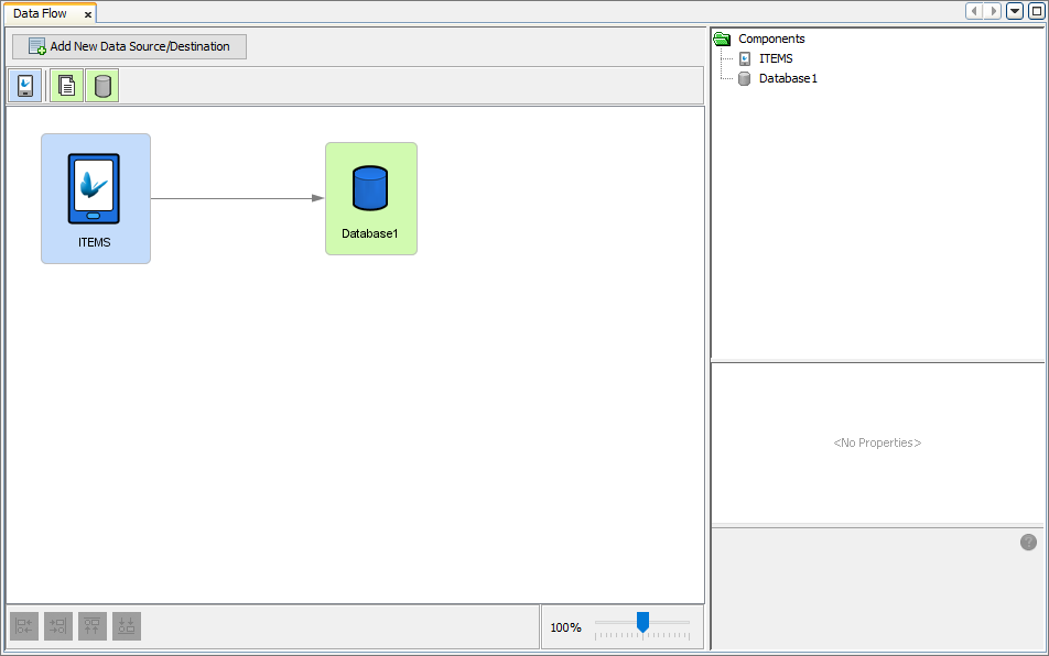
Data Flow Canvas
Within the Data Flow Panel, the canvas can be seen displaying all
the nodes and the Data Flow Links currently created for the BXP project.
By using the top toolbar found in the Data Flow Panel ( ), client tables and other
data accessor nodes can easily be dragged and dropped to create them
on the canvas. Once on the canvas, these elements can be rearranged
into any position by clicking and dragging them with the mouse. The
alignment buttons found on the bottom left of the Data Flow Panel
can be utilised to position these elements as well. Zooming into the
canvas to have a better view of the elements in the data flow is also
made possible through the zooming dial found on the bottom right of
the Data Flow Panel.
), client tables and other
data accessor nodes can easily be dragged and dropped to create them
on the canvas. Once on the canvas, these elements can be rearranged
into any position by clicking and dragging them with the mouse. The
alignment buttons found on the bottom left of the Data Flow Panel
can be utilised to position these elements as well. Zooming into the
canvas to have a better view of the elements in the data flow is also
made possible through the zooming dial found on the bottom right of
the Data Flow Panel.
Create Data Flow Link
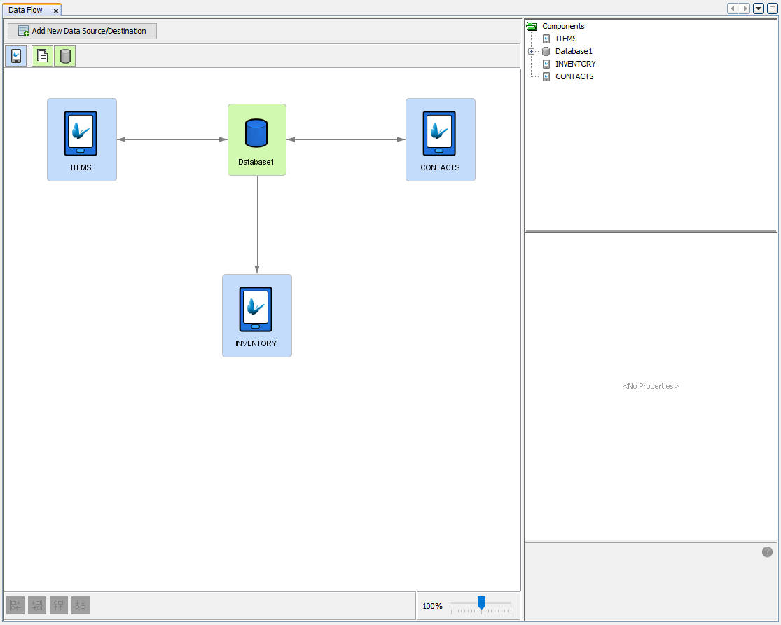
Data Flow Links are used to provide a visual representation of data flow between client tables and data accessors. These links can easily be created by pressing the 'Ctrl' button and dragging the mouse from one node (the source of data) to another (the destination of data). The direction of data is further reinforced through the directional arrow displayed indicating which node will be sending data and which will be receiving data or even both. The link will snap to position if the connection is valid, indicating the successful creation of the link. The direction of data flow must be between client tables and data accessors ONLY. Data Flow Links can be in either direction (client to server or server to client), provided the source and destination of data can accept the connections in the direction created. However, with file data accessors, data is only allowed to flow in one direction.


The above Data Flow Links demonstrates all the different Data Flow Links that can be created and how Data Flow Links can be bidirectional between database data accessors representing the fact that data can be sent and received in both directions. However it should be noted that this feature is not available to file data accessors in which only one direction of data flow is allowed.
Create New Data Source/Destination
The Data Flow Panel also provides another avenue to create data
flows with the required source and destination nodes. A wizard for
defining all that is required for a Data Flow Link is stepped through,
allowing valid Data Flow Links to be created easily without missing
any important information. The creation wizard can be assessed by
pressing on the  button.
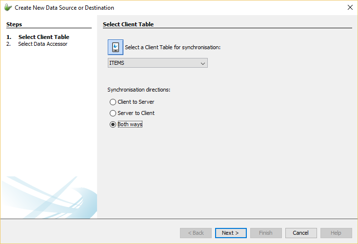
Once the wizard is opened, the first step is to select the client table to be used in the Data Flow Link. A drop list can be used to select the client table out of the already defined tables in the project. The direction where data will flow will also need to be defined indicating which sync point will receive and/or send data will also need to be specified. The direction of the synchronisation can be either 'Client to Server', 'Server to Client' or 'Both ways'.
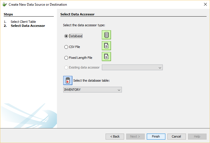
The next and final step is to select the data accessor to be used in the link. Here the type of the accessor can be selected and set. There exists two main types, database accessors and file accessors. Each data accessor type requires different information in order to be successfully connected to when synchronisation is performed. Database accessors are the only type of data accessors that can be used for two-way synchronisation or bidirectional flow of data. If a bidirectional Data Flow Link is attempted to be made with a file accessor an error message will appear and will not create a Data Flow Link. File accessors are allowed only unidirectional flow of information as to provide data integrity due to concurrent access issues when reading and writing to a single file. Once all valid settings are provided, the Data Flow Link will be created and displayed on the canvas.
Through this step in the wizard, the data accessor type can be chosen and data accessor nodes can be created. The possible choices are
Database: This is essentially a database data accessor which indicates the server side data accessor will be a database table within the specified database.
CSV File: A type of file data accessor in which the file to be the data sync point will be a csv file that will contain a delimiting character that separates fields within a record line.
Fixed Length File: File data accessor type which indicates the file data source/destination will be a file with fixed length where a mapping field specifies a section of a file line with a starting positon and the length of the field.
Existing data accessor: Allows for existing data accessors to be chosen as the data accessor. The drop down menu will be populated with all the valid data accessors that can be selected.
By selecting the required type, more specific options will need to be set such as the table within the database to be used. These other options will automatically appear within the wizard and will need to be given valid values before the creation of the Data Flow Link.
By pressing the 'Finish' button, the details of the Data Flow Link will be validated and if valid, the link will be created otherwise an error message will appear within the wizard. More information about data accessors can be found in the File Data Accessor and Database Data Accessor sections below.
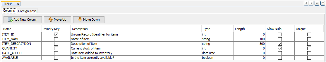
Client Tables 
Client tables represent the table data within the BXP project used by the BXP application. Within the Data Flow Panel, they may be used to edit Application tables, and also define synchronisation of these tables to and/or from the server defined via nodes and links on the canvas. Client table nodes can easily be identified by the blue background colour.
Tables created via the BXP Application panel dialogs will appear in the Data Flow Node as client tables. The links in the panel define the server sources or destination for the device records when the application synchronises to the server. Client table nodes may not have any links defined, which means that no synchronisation is required for the table. For more information on manipulation of tables refer to the Data Tables chapter.
Client tables may also be added to the data flow by dragging and
dropping the client table icon (![]() ) from the top
toolbar into the Data Flow Canvas.
) from the top
toolbar into the Data Flow Canvas.
When this is done the 'New Table' wizard will appear requiring the name of the new client table to be entered. Once completed, a new client table will be created within the project that is available to be used within the Data Flow and Application elements of the BXP project. Through this wizard, a description of the table can also be specified. However client tables defined this way will initially have empty definitions (i.e. no columns). In order to modify the definition of a table, the client table node can be double-clicked in order to open the client table editor. Through this editor, the full definition of the client table can be defined. All the data columns can be defined with their desired properties catering to their required definitions.
Caution should be taken when modifying an existing table definition when in use elsewhere in the project (such as in form dialogs in the Application element), as editing these definitions can cause errors within the project that will need to be rectified and fixed before publishing of the application.
Additionally, client tables can be deleted through the Data Flow Panel. They can be deleted either by pressing the 'Delete' button on the keyboard or right-clicking the node and selecting the 'Delete' menu item. Similarly when modifying table definitions, caution is needed when deleting tables that are currently being used within the project.
Client Table Connectivity
Within the Data Flow Panel, client tables can be connected to and from file data accessors and/or database data accessors in order to carry out synchronisation between these sources of data. These Data Flow Links are required to match the sources and direction of synchronisation outlined within the sync dialogs of the application.
In order for synchronisation to be added to the application, sync requests will need to be defined within Sync Dialogs. If the application is defined using sync requests in order to distribute data, matching Data Flow Links will need to be created to indicate the source and destination of data. For instance, if a sync requests has been set to 'Upload' data from a client table, a Data Flow Link from that corresponding client table node to the data source accessor on the server must be defined in the Data Flow Panel. If these details are not specified within the data flow, an error will occur when synchronisation is executed on the device and the server. Client tables are restricted to having only one input and one output Data Flow Link that can be customised to connect to any other data accessor all depending on the sync requirements of the project.
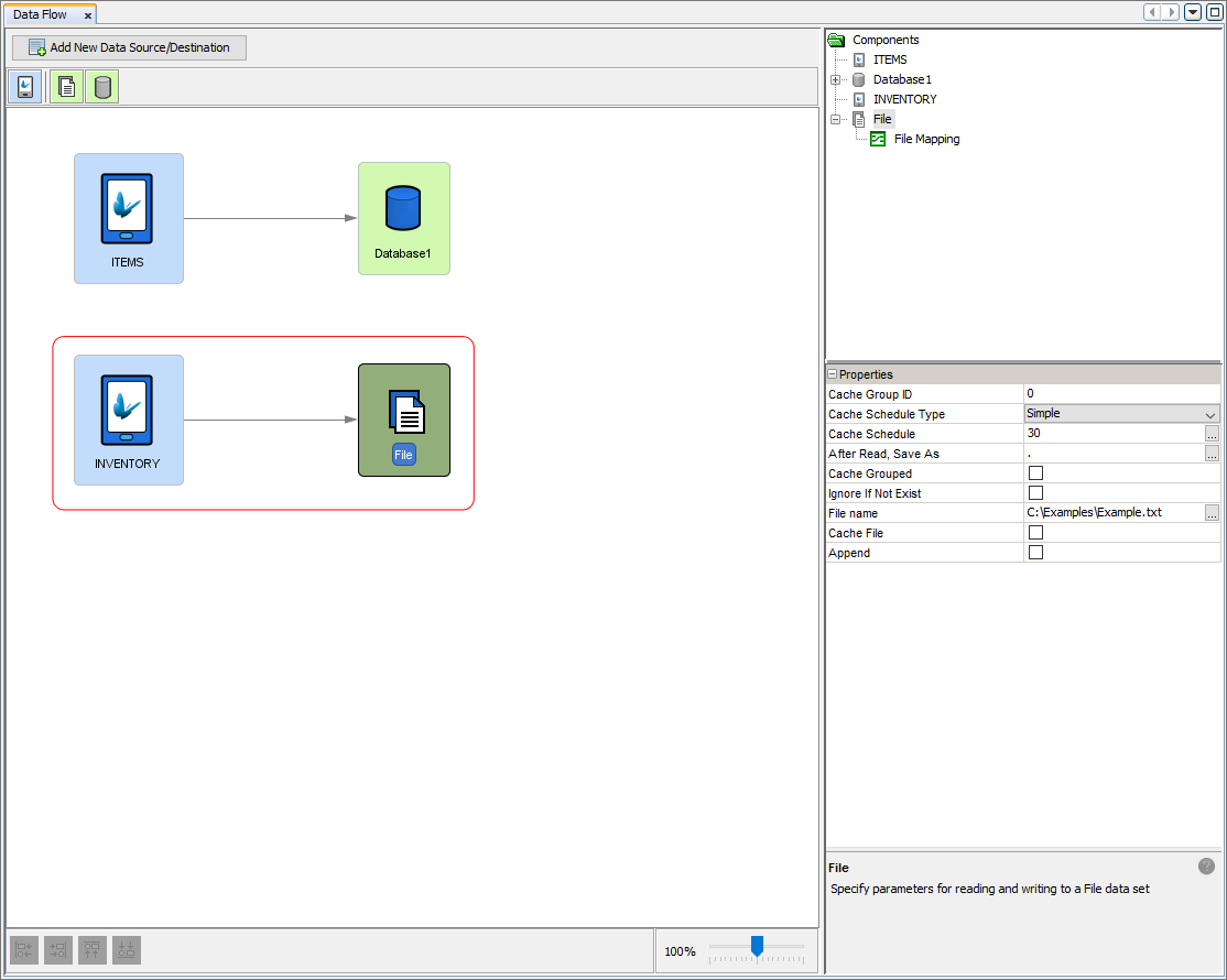
File Data
Accessor 
File data accessors defines a single file for reading and writing server data when used for synchronisation. They represent files that can be accessed from the server which either acts as a data source for records sent to clients, or a destination which will write records received from devices to the file itself. These files can be CSV files or fixed length files. However, a file data accessor cannot be used for bidirectional flow of data meaning they are restricted to only having either one input or one output Data Flow Link to a client table. This restriction is put into place to prevent concurrent operations on the single file preventing data inconsistences and ensuring the integrity of the file and data.
By clicking on the file data accessor node, the properties of the file accessor will populate the properties panel in the Data Flow Panel. Here the details of the file can be specified. The file itself is defined by the 'File name' property. The file name property specified in the file to be used in the synchronisation so proper permissions should be set to allow the server read and write access to the file. Further properties can be managed such as the 'Append' property. When this property is ticked, new data to be written to the file will be added to the end of the specified file, otherwise if unticked, the existing contents of the file will be overwritten with the new server data received. Another useful property is the 'Ignore If Not Exist' where left unticked and the file is set to be read but does not exist then an error is produced on the server. However if it is ticked, then the fact the file does not exist is ignored and no error is thrown.
Mapping
File data accessors require a mapping in order to interface with client tables. Mappings will be used to detail the expected format of the file when the data in synchronised and saved to this file on the server. Through mappings, the specific format of data can be manipulated in order to match the correct format of data for both the client table and the file. When a Data Flow Link is created between a file data accessor and a client table node, a mapping is automatically created in which default mapping will be instantiated. This default behaviour will treat the file like a CSV file where column values will be separated with commas and saved into the file. By double clicking the file data accessor, the mapping editor will open with the current mapping. Through this editor, mapping of data between the client table and the file can be edited and specified. There are currently 2 types of mappings.
CSV File Mapping: CSV (Comma Separated Values) file mappings provide the details of a CSV file layout, mapping each comma separated value to client table columns.
Fixed Length File Mapping: Fixed length file mappings are used to map a fixed length file layout to a device BrightForms table. Each mapping field specifies a section of a file line with a starting position and the length of the field.
For more information refer to the Mappings chapter.
Database
Data Accessor 
A database data accessor represents a database connected with server tables that can be accessed as a sync point to be used to synchronise data with client tables. It can be as simple as a Microsoft Access database or full fledged relational database such as Microsoft SQL Server, Oracle, or IBM DB2. Database accessors are similar to file accessors where they are both used in order to share and receive data for synchronisation. However as opposed to files, database accessors have the ability of allowing bidirectional flow of data between itself and client tables (i.e. database tables can send and receive data). Hence multiple client tables can use the same database as the source or the destination of data. In order for synchronisation to succeed, the client tables must also exist in the database for records to be saved to or read from. Database data accessor nodes can easily be created by dragging and dropping the accessor icon onto the data flow canvas.
Database Definition
For synchronisation to be carried out, the details of the desired database to be connected to must be defined. Through these details, the server will be able to access the database in order to retrieve or save data into the defined table/s. Defining the properties of the database to connect to is made simple through the Database dialog. Through this window the database type can be chosen and according to this type, the required details needed will populate the dialog. If the desired database type is not included in the drop down list, the type "Custom" can be chosen and a JDBC driver can be specified. JDBC stands for Java Database Connectivity with the purpose of providing an interface for clients to access a database. If it is required, the JDBC database driver must be placed into the 'lib' directory under the install directory of BrightServer.

If the correct database details are entered, the server will be able to connect and work with the data source. If tables do not exist in the database, through BrightBuilder, table definitions can easily be created to ensure consistency between database and defined projects in BrightBuilder. By right-clicking the BXP project, 'Create Database Tables' and 'Import Database Tables' options can be used to create tables in the database and also import table definitions into the BXP project.